DandySolutions
Thoughts and Ideas from Andy M
I have been creating things since
high school. This website will
eventually have as many of those ideas as I can document.
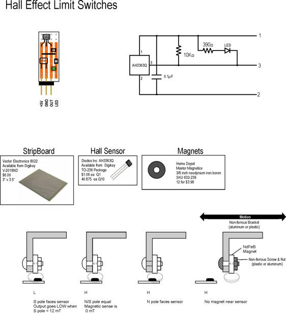
Hall Effect Switches
I had a project that needed
limit switches that were non-contact and could be water/solvent proof. Optical was a possibility but I was worried
about fluid spray causing false readings.
I had previously used Hall
Effect sensors in a project but those were analog, producing a voltage
proportional to distance. That would
work but it would require measuring a multitude of voltages. Having previous experience with voltage
sensing I wanted to see what else I could dream up in the digital world.
Looking
through the available Hall Sensors, there was a class of sensor that output a
digital signal, send 1 for one magnetic field and 0 for another field
level. Those sensors came in two general
types. Type 1 was referred to as bipolar
latch. It’s output went high (logic 1)
when a north pole of a magnet approaches and low (logic 0) when a south pole of
a magnet approaches. If no magnetic
field is present, the device remains in the state (1 or 0) it was last set to.
Type
2 was referred to as a unipolar switch. If
no magnetic field is present, the output will be high (logic 1). As a south pole approaches, when close enough
the output will go low (logic 0).
Bringing a north pole to the switch causes it to remain in the high
(logic 1) state, the same as no magnetic field.
If
a magnet passes sideways near the switch with the north and south poles aligned
along the axis of motion and the north pole approaches first, the switch will
be high until the center of the magnet passes the switch. Before it passes by, the north pole will
cause a high output. As it passes and
the south pole faces the device, the output will go low. The choice of the Type 2 sensor is vital
because it establishes the output state when the magnet is far away from the
switch.
This
sensor will also work if the south magnetic pole approaches first but the
accuracy will ne much less. This is
because the sensor is measuring the strength of the magnet as it
approaches. The strength of the field
will increase as the magnet approaches.
As the magnet moves away, the sensor will eventually drop below its hold
field and go high but the activate point and the release point will be fairly
far apart.
If
the magnet approaches north pole first, as the body of the magnet passes the
sensor, the field will reverse (north to south) just as the centerline passes
giving a very sharp switch point. Going
back the other way gives an equally sharp change from south back to north.
I
make the sensor boards using stripboard.
I cut a piece of the stripboad with 4 copper traces on it. I put an led on the board so that I can
visually comfirm proper operation without consulting the monitoring
equipment. I use the small square pin
connectors for connection and the choice of ground in the middle keeps damage
from occurring if the connector is installed reversed. It won’t operate but reversing the connector
will fix the issue with no blown parts.
If
you have never used stripboard, look online for information about using
it. It is very useful to have a 7/64
inch drill bit in a small hand chuck.
You need this to ‘cut’ the traces where required. An electric drill is too hard to control and
often results in a hole through the board.
Since
these sensors are magnetic, and shielding like plastic tubing will cause no
problems. Some sensing works through
thin wall aluminum tubing if you need that much shielding. Also note that the neodymium-iron-boron
magnets are MOSTLY iron and thus will rust.
The factory plates them with nickel to prevent this but I have found
that the nickel plating is porous and rust through it possible. If you expect the magnet to be water
wet, coat it in a waterproof
coating. Epoxy or silicone sealant if
repel water and have no effect on the magnet field.
Diagram
2
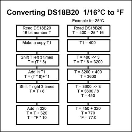
The DS18B20
Temperature Sensor and Fahrenheit
I
have used several different temperature sensors in the past, like the LM76 and
others so when the DS18B20 came out using a one-wire interface, I immediately
bought some to test. Writing the code
was fairly easy until I wanted the result to be in °F. If you are working in a language with
floating point math, it is easy to follow the old conversion:
°F
= (°C * 5 / 9)+32
The
problem I had was the system I was creating was based upon an Atmel AVR
microcontroller and the entire program storage space was less than the size of
the floating point libraries available.
So I tackled the problem of doing this conversion with only integer
arithmetic and an 8 bit CPU.
First
thing was that the DS18B20 produced temperatures in 1/16 degrees C. That roughly corresponds to 1/10 degree F so
a conversion from 16ths C to 10ths F was the solution. Since the DS18B20 produced 1/16ths C and
those 16 16ths corresponded to 18 10ths degree F I needed a ratio conversion of
16:18.
16:18
can be reduced to 8:9 (divide by 2) so the conversion needed was to multiply
the DS18B20 output value by 9 and then divide by 8. Multiply by 9 is easy: multiply by 8 (three shifts left) and then
add in the original value (*9 ≡ *8
+ *1) and then dividing by 8 is easy, three shifts right. Oh, and then add in the constant 32 which is
320 because we are counting in 1/10ths F.